|
Objectives:
- To become familiar with the use of a GPS receiver
- To get a physical feel for the accuracy of an individual
measurement
- To learn how to import GPS point data from an Excel workbook
into ArcMap
- To learn to extract point coordinates (Eastings, Northings)
from a point shapefile
Exercise:
This exercise entails the following steps:
A. Preparing a map for use in the field
1) Copy the Lab_8_data folder to your storage space and then open the
East Mall map document in that folder. The
Spatial Reference for the map is NAD83, UTM zone 14N. The
map contains two layers: a 1 foot resolution DOQQ (note that as with
all DOQs, 1 foot resolution refers to sampling size of the pixels, not
the resolution of the original photograph) that covers part of the East
Mall of the UT campus and
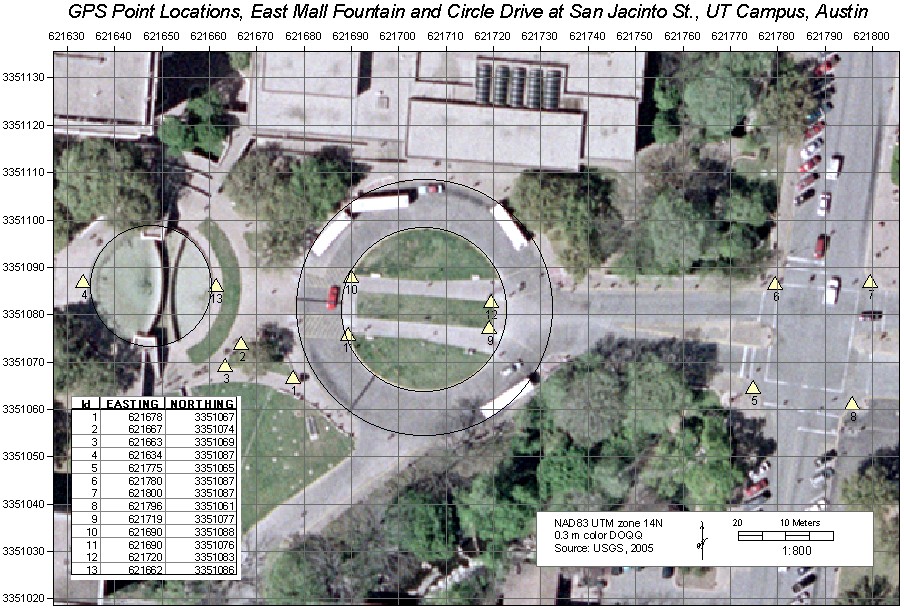
a feature class of 13 GPS target points – points that you will record the
positions of with your GPS receiver. The Data Frame has been fixed to a
scale of 1:800 and the page layout should be “landscape” mode to show
all 13 points. A 10 meter NAD83 UTM grid overlies the layout. Leave the
map in Layout view.
2) Edit the attribute table of the GPS points to create two new
fields called EASTING and NORTHING. The field "Type" should be "Long
integer to allow for 6 or seven characters in the Easting and Northing
fields. If this were a stand-alone shapefile, you would also need
to specify the precision, which should be 7 or greater.
3) Populate the new field using the field calculator and the VBA
scripts from EasyCalc50 called “Point_Get_X.cal” (for EASTING) and “Point_Get_Y.cal”
(for NORTHING).
These files can be found in the class folder, on the path \Programs\Arc_Extensions\EasyCalculate50\ec\calculate.
See Software Tip 6 if you’ve forgotten how to do (or haven’t yet done)
this.
4) Narrow the table field widths to the minimum that will still show
the values, then from the table Options button “Add Table to Layout”.
Before doing so, hide (uncheck) the FID and Shape fields using the
Layer Properties Fields tab settings.
5) Move the added table frame to the lower left corner of the
layout, adjust its size to a minimum, and fill the frame background with
white (right click when the new frame is highlighted to bring up its
Properties, then modify the Background to white). Your completed layout
should look like that below.
6) Create a 10 meter UTM grid for the layout, like that shown below
in the example.
7) Print it in color for use in collecting your GPS data.
B. Collecting the GPS data
1) Delete all waypoints, tracks and routes from your receiver (Garmin
units). To delete all waypoints, go to the "Find" screen, open the
options, and delete all points.
2) With map and GPS receiver in hand, go out and log a waypoint at each
of the 13 target locations. You should be able to locate each of these
points fairly precisely simply by carefully examining the photo. They
were chosen using an obvious landmark, e.g. the intersections of sidewalks,
road corner, sidewalk or road edges, etc.
Log a single point ("waypoint") at each location, taking no particular care to do
so. We are interested in the precision of a single reading and thus want
spot measurements, not time averaged readings. Data collection should
take no more than 30 minutes.
C) Downloading data from the receiver
For a Garmin E-trex receiver:
1) Connect the download cable to the receiver and the serial port on
the back of a computer. Note: the computers in the class
room no longer have serial ports. A laptop with a serial port will be
available in the classroom; you can also use the older computers in the
undergraduate computer lab to do this.
2) Turn on the receiver, go to the main menu/setup/interface and
ensure that the Serial Data Format is set to Garmin.
3) To download waypoints from the Garmin receivers we will use
DNRGarmin, an excellent freeware program from the Minnesota
Department of Natural Resources. A zipped install file for the
software is located in the class folder in the "Programs" folder.
Excellent help is available in the Help Menu of the program, but nobody
reads help files....
With the receiver on and the cable connected to a computer, do the
following:
- Start the DNRGarmin software - it will detect the receiver and
present a window like the one shown below.
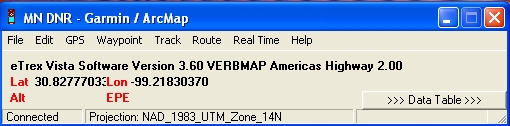
-
From the "Waypoint" menu, select "Waypoint
Properties..." and from the Waypoint tab uncheck the fields that you
don't want to keep, basically all but the required ("type",
"indent", "lat", "lon", "y_proj"," x_proj", "time") and "comment"
fields. Examine the other tabs if you like but no changes are
needed for this exercise. Close the Properties window.
-
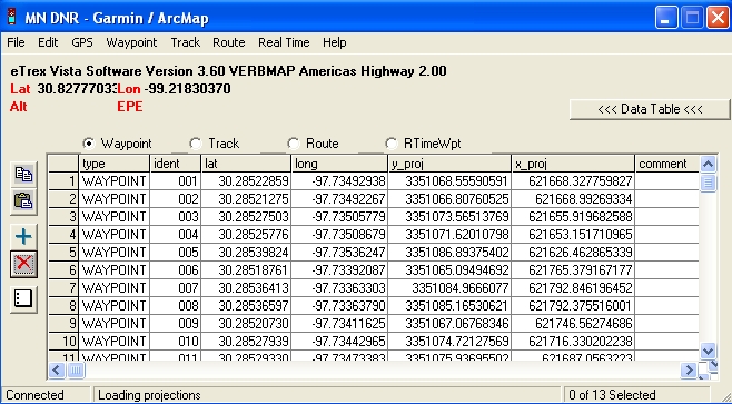
From the "Waypoint" menu, select "Download".
This will download all waypoints to the DNR software and display
them, as shown below.
-
From the "File" menu, select "Save To > ArcMap >Shapefile
Layer..." and give the shapefile a name and location (save it to a
USB flash drive).
-
Exit from the DNRGarmin software.
E) Waypoint Shapefile in ArcMap
1) Check the spatial reference of the shapefile in ArcCatalog to
ensure it is the same as the one you used to collect the data. If
not, clear it and define the proper spatial reference (see
Lab 2 if you've forgotten how).
2) Reopen the East Mall map document and add the waypoint shapefile
to it.
3) Symbolize the data, as desired, for comparison with the actual
locations of the readings.
|