|
8.1 Objectives
The primary goal of our field trip this weekend is to locate, as
accurately as possible, the main trace of the Mt. Bonnell Fault where it
transects the Barton Creek Wilderness Preserve. Published geologic
maps, which you will have with you in digital form, indicate three
different locations for the fault. Your job will be to determine which,
if any is correct. You will document your findings with
geo-located digital photographs and field observations, as well as your
own well-located fault trace (or traces). Lecture handouts
distributed this week provide background on the Cretaceous carbonate stratigraphy affected by faulting and
outline how we will accomplish
our goal.
Because of dense vegetation, one of the principle challenges will be
staying located. The mapping-grade GPS receivers you will use will
be invaluable in this regard, but you will also need a gridded, color,
geologic map on paper as a backup. You will prepare such a map as
part of this exercise. We will also need a few empty point and
line files to store observations - these you will create as well.
Once these tasks are complete the GIS data will be transferred to the GPS units. A second section of the lab (Part
B), to be done during class Thursday, briefly describes the ArcPad
software we will use for data gathering and a practice data collection
exercise to be completed before heading out this weekend.
8.2 Data Sources
All field trip vector data are in a geodatabase in the Lab_8_data
folder. A hill shade and elevation raster are stored separately in
the same folder, as is a map document. The data are from the
following sources:
1) Geologic map data and layers:
a) Geologic Quadrangle Map (1:24,000) No. 38 - Austin
West, Travis County, TX by Rodda, Garner and Dawe, Bureau of Economic
Geology, UT Austin, 1970. Data from this source contains "AustinW_"
as part of the file names.
b) The Geologic Atlas of Texas Austin Sheet,
1:250,000, Bureau of Economic Geology, 1974. The file, "GAT_faults"
is from this source.
c) Geologic map of the Edwards aquifer recharge
zone, southcentral Texas: U.S. Geological Survey Scientific
Investigations Map 2873, scale 1:200,000 compiled by Blome, C.D., Faith,
J.R., Pedraza, D.E., Ozuna, G.B., Cole, J.C., Clark, A.K., Small, T.A.,
and Morris, R.R., 2005. Data from this source have file names that
begin with "EA_".
2) Roads and Park boundaries:
City
of Austin GIS data
3) Airborn LiDAR elevation data -
TNRIS
and the
Capital Area Council of Governments. These bare-earth point
datas, in .las format, were used to construct a high resolution TIN that
was then converted to a 1.8 m-resolution DEM raster ("bc_elev").
The hill shade of this raster is "bc_hshade".
4) A vector stream file ("BCWP_streams") was created by
digitizing, using the hill shade raster as a guide.
5) Trail data within the Barton Creek Wilderness Preserve ("BCWP_trails")
were collected by Dr. R. Marrett with his cell phone while hiking, as
were data points where interesting geologic observations can be made ("Marrett_pts").
The spatial reference for all data is UTM zone 14N, NAD83.
A single spatial reference for all data is required for later use with
ArcPad - it is not capable of on-the-fly projection.
8.3 Modifying the Geodatabase for Field Work
- Download the Lab_8_data folder to your personal storage space.
- Open "BartonCr_327G_project.mxd" and examine the files in the table
of contents.
- Using ArcCatalog locate the geodatabase "BartonCr_Field_Trip_data"
and create within it two feature classes, one for points called "XX_Points"
(substitute your initials for XX) and another for lines called "XX_lines"
again substituting your intials for XX. Specify the coordinate
system for both as UTM zone 14N, NAD83 and accept the default XY
tollerance.
- Create two new fields in the point feature class, one called "Type"
(to specify the type of data collected at the point) and another called
"Notes". Specify both as Text fields with a Lengths of 25
characters. Create a third field called "Unit" with Data Type =
text and a Length of 7 characters. This field will store rock unit
abbreviations.
- Do the same for the XX_lines feature class.
- Create a Domain (by right-clicking on the BC_Field_Trip_data geodatabase icon, then Properties...) called
PT_TYPE, (Field Type is Text) that is a coded-value domain containing the coded values of
"photo", "observation", and "other" (see Lab
4) and then attach this domain to the XX-Points attribute field
TYPE
(again see Lab 4).
- As above, create a coded-value Domain call "LN_Type", (Field Type is
Text) with coded values of "fault", "contact", "axial_trace acline" and
"axial_trace_scline" and attach this domain to the "XX_Lines" attribute
field "Type".
- As above, create a coded value Domain called "Unit_Abbr" (Field Type
is Text) with coded values of Kgr2, Kgr3, Kgr4, Kgr5, Ked1, Ked2, Ked3,
Ked4, Kgt and unknown. Attach this domain to the "XX_Lines and
XX_Points attribute field "Unit".
Congratulations, you have now completed the modifications to the database you will need for
this project.
8.4 Making Field Maps, preparing for export to ArcPad
- In the interest of time, a 1:10,000 scale field map
has been prepared for you and is ready to print.
If not already open, open the
"BartonCr_327G_project.mxd", go to Data View (if not
already there), and use the "10K field map" Bookmark (a
menu item at the top of screen) to get the appropriate
map area on the page.
- Print the map in color and don't forget to bring it
with you this weekend.
- Bring your newly created line_XX and point_XX Feature Classes
into the map and move them to the top of the Table of
Contents.
8.5 Trimble Nomad and ArcPad v. 10
GPS data collection using the Trimble Nomad units is done with ArcPad software. ArcPad is a streamlined version of ArcGIS
that is equipped with very easy to use GPS capture tools. ArcPad 10 is
installed on the classroom computers and our field data collection units. Version
10 is a major revision
from earlier releases. Before getting a little ArcPad
practice, we first need to convert the ArcGIS map document file into an
"ArcPad Project". An automated tool exists to do so, which converts
most rasters to jpeg images, the geodatabase to an ArcPad exchange format
database (.AXF),
and makes data entry forms from the domains for each Feature Class.
We can "check out" the empty Feature Classes for editing then, upon
return, "check in" the same, permitting the software to automatically
update the geodatabase!
An important note for future reference about ArcPad versions:
- ArcPad 10 represents a significant departure from earlier
versions (i.e. 8.x and below). "ArcPad Projects" created for ArcPad
10 will not run on 6.x software, and vice-versa.
The ArcMap toolbar for creating ArcPad projects in versions of
ArcGIS 9.1 and higher contains separate tools for creating ArcPad 8.x and 6.x (or lower) projects. It is thus important to know
which version of ArcPad is installed on your field data collection
units. Our Trimble Nomads and Xplore tablet PCs are
currently running ArcPad 10, as are
the computers in the lab.
A. Preparing the Map Document for ArcPad (version 10).
- Open your map document.
- Switch to Data View mode (if you're in Layout mode) and zoom to the
"Area_outline" layer. This is an important step!
- Make sure the "Point_XX", "Line_XX"
Feature Classes
are present in the Table of Contents of the map. These are empty, but have coded-value domains already
built that will allow use of ArcPad data entry forms. These are
the files you will populate with GPS measurements.
- Change the symbology of these files to colors/symbols that will
be recognizable on both a white background and the geologic map. Red works
well, as does light blue. Remove the outline from the point symbol
and make it a little bigger, e.g. size 6. his is much easier to do now than later
in ArcPad.
- If not already on. Turn on the ArcPad Data Manager
toolbar (Customize>Toolbars...) shown below.
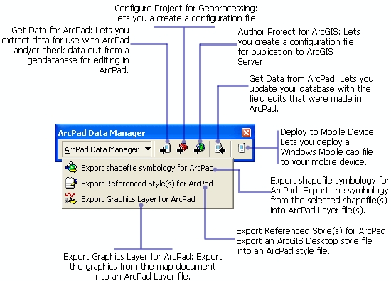
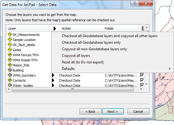
- On the ArcPad toolbar, click the "Get Data for ArcPad" button.
In the "Select Data"
window, shown below, there are several options for how to export data
under the "Action" column. The "action" performed
on each layer can be set individually or for all layers
by clicking on the word "Action" to display the menu
shown in the figure below. Strictly speaking, we
can either "Checkout" a layer for editing or "Copyout" a
layer. A "Checkout" is only allowed for Geodatabase
layers; shapefiles or other layers not in a geodatabase
can be "Copied Out". A "Checkout" creates a compact
geodatabase that can only be read by ArcPad in a so-called "AXF"
(Arc Pad Exchange Format) file. There are
numerous advantages to AXF files - read about them on
page 573 of the ArcPad Help PDF in the Lab 8_data
folder. For our purposes, the principal advantage
is the automatic creation of forms (based on our geodatabase domains)
that can be edited in the field, and the ability to directly import the
results into our ArcGIS project after returning from the field.
The main disadvantage is that a Checkout is tied to a specific ArcGIS
file, your project, on a specific computer. After data
collection, the file can only be checked into your
project (into your
geodatabase) on the computer you created it on. An AXF file can
not be edited by any software, so if you are unable to check it back in,
for whatever reason, you've lost all of your field results.
The other option, "Copyout", creates a Shapefile that can be read by ArcPad. Unfortunately, this option does not automatically create
forms for field editing, nor can results be directly checked back into
your ArcGIS file after field work is done. The shapefiles can,
however, be downloaded from the receiver onto a computer and loaded into
your ArcGIS project by the same process you would use to load any other
shapefile. "Copyout" layers are exported to ArcPad as "background
layers" that either can be editable or not.
We will cover several bases by "Checking Out" the two files we will
edit in the field (Point_XX, Line_XX) and "Copyout"
all other files (those we will not edit) as "read-only" background
shapefiles. I will explain the rationale during lecture. To
do this requires specifying the "action" for each layer individually.
- Click the black arrowhead to the left of your "Line_XX"
layer and choose "Checkout for disconnected editing in ArcPad>data based
on defined extent". Do the same for the Point_XX
layer.
- For all other vector layers choose "Export as Background data (to
shapefile)>Make Read Only"
- Do not export any of the raster files EXCEPT "bc_hshade"
which should be exported as a Background JPG2000.
- Click Next.
- The next window, "Select Picture Options", is not
applicable to this project; Click Next.
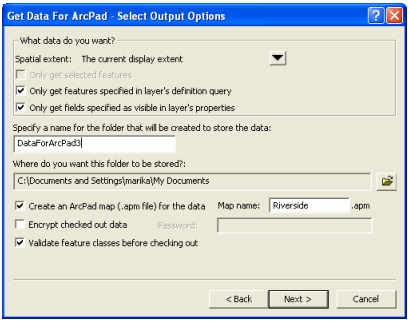
- The final window lets you set the spatial extent (current
display extent or full extent of the layers), lets you select whether to
limit the fields to those that are visible in the attribute tables and
the features to those specified in the layer's definition query, lets
you specify a name for the folder that will store the data, and lets you
create an ArcPad map file (the equivalent of an .mxd file) for the data,
as shown in the "Get Data For ArcPad" screen capture below.
- Enter a name for the folder, e.g. "ArcPad_BC_XX" (where
XX are your initials) and a
Map Name that includes your last name or initials (e.g. BC_map_XX).
- Making sure first that your display shows the entire area of
interest (i.e. you are zoomed to the "Area_outline" layer), make the selections shown in the figure below, setting the
"Where do you want the folder to be stored?" to an appropriate location
on your network storage space.
- Click Next, the Finish, and wait for the data to be created.
- With my help , transfer your new "ArcPad_BC_XX" folder
to your Trimble Nomad (these will be shared, but each partner can load a
project). The Nomad units have a folder called "My
Documents" that should be used for all ArcPad
data and files.
- Print a color copy of the PDF file "ArcPad Quick Reference", in color,
from All Programs>ArcGIS>ArcPad 10>Help>ArcPad Quick Reference.
You will find this exceptionally useful for Part B of this lab, and for
the field trip.
Part B: Practice with ArcPad in the field
8B.1 Using ArcPad - some practice with the basics
Editing in ArcPad is, in most ways, much simpler than Editing in ArcGIS.
The basic concept is the same in both - data are entered into a file that
is open for editing. Below are a few of the basics. A complete description of the
software can be found in the ArcPad 10 folder in the class folder.
- On a classroom computer, open ArcPad 10 from the Start Button>All Programs menu in Windows.
- Click the folder button at the top of the ArcPad window and select
"Open Map", then browse to your ArcPad map file, the one with
the ".apm" extension, in your "ArcPad_RR_XX" folder.
- Five toolbars are immediately available (called Main
Tools, Browse Tools Edit Tools Quick Capture and Navigation), though
only one at timeis displayed (this saves real estate on small
screens).
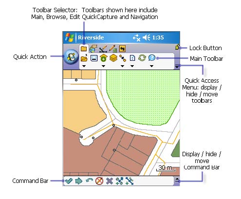
- Click the Main Tools icon (on the left in the figure above) and then
select the Layers icon
 to
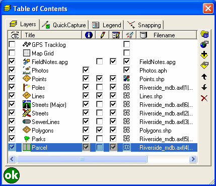
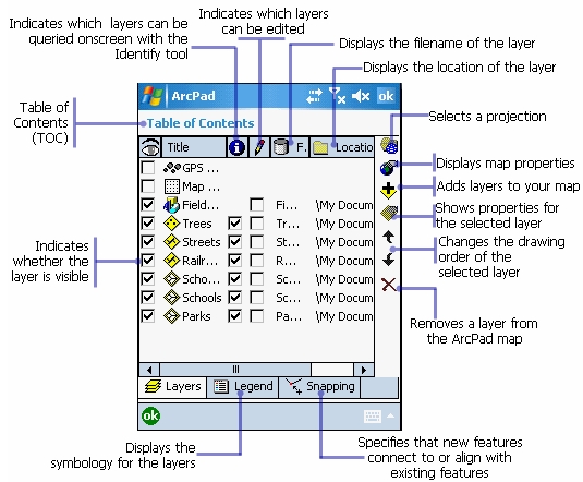
open up a Table of Contents, like that on the left below. The
diagram on the right, from an earlier version of ArcPad, has many of the
icons labeled. to
open up a Table of Contents, like that on the left below. The
diagram on the right, from an earlier version of ArcPad, has many of the
icons labeled.
-
The check boxes on the left in the "eye" column turn
layers on and off for viewing. The check boxes in the "pencil"
column turn layers on and off for editing. This is similar
to setting the "Target" of the editing toolbar in ArcGIS, except that
in ArcPad more than one layer can be open for editing at a time. In
the Table of Contents to the right above, none of the layers are open for
editing. In the table of contents on the left above three layers
(Point, Line, Polygon) are open for editing. Finally, the check boxes below the Info icon (i) make layers available for query.
Layer Properties can be accessed by an icon on the right, as can other
options denoted by icons that should be familiar from ArcMap. The
column with the "rocket ship" icon at the top is the QuickDraw mode;
checking boxes here allows the different layers to be drawn to different
"coarseness" so they will render quicker on screen. The QuickDraw
mode is accessed from the Editing Toolbar.
-
Turn on the "Point_XX" layer for editing and close the
Table of Contents.
-
Turn on the Edit toolbar by selecting it from top row of
icons, as shown below.
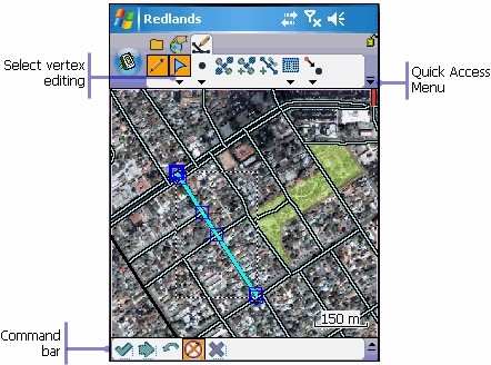
-
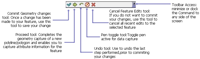
The function of the edit tools are shown in the figure
below. This is the most important toolbar for the field work
this weekend. Learn it.
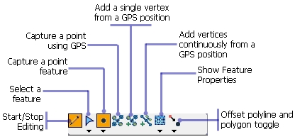
To add a point to the map, Click the pencil tool, select
the layer you want to edit, click the "Capture a point
feature" button, (Capture of polyline or polygon features, if open
for editing in the TOC, can be selecting from the drop-down menu below
the "capture a point" feature icon). Then click a location on the map. A data entry form should then open,
allowing you to select the feature name from a drop down list.
To do outdoors: To add a GPS location as a point, click instead the
"Capture a point using GPS" button. (When the GPS is active this
button is not grayed-out.)
-
To add a line, click the Pencil icon, select the polyline
feature class you want to edit, click the drop-down arrow below
to the "Capture a point feature" button, and select "Polyline".
Click on the map where you wish to place a polyline vertex, click and drag
on the next spot where you want a vertex, and continue this process until
finished. The line is not completed until you click the "Proceed
or complete feature" button at the bottom of the ArcPad window
(shown below).
-
To do outdoors: To add GPS vertices to a polyline, as above, click the "Capture a polyline"
button (beneath the capture a point button), click the "Add a single
vertex from a GPS position" button and continue clicking this button
every time you want to add a vertex to the line. To finish the
line, click the "Proceed or complete feature" button, the
green arrow icon. The line is not completed until you click the
"Proceed or complete feature" icon.
The GPS must be activated before
the GPS buttons are available.
-
A similar procedure is used to capture polygon vertices
with and without GPS.
-
You can delete features by selecting them with the
Arrow button (shown above) and then
clicking the "Edit vertices" button.
-
Practice adding and deleting lines, points and polygons to the map.
Name the features test1, test2, etc. so that, if needed, you will be able to recognize and
delete them later.
-
Browse the ArcPad manual in the digital books folder,
particularly the sections on editing. Download and print the
ArcPad Quick Reference
page.
-
Before loading your Barton Creek ArcPad folders to the field GPS
units, clear each of your test features, or don't save your project after
editing.
8B.2
-
Before our field trip, you need practice using ArcPad with a GPS.
An ArcPad project for the Main Building area, identical to the ArcGIS project
you constructed in Lab 6, is loaded on all instruments. Take
your instrument outside, open the Main Building project, and practice
capturing lines, points and polygons using the ArcPad GPS
tools described above.
-
Specifically, capture the features listed and
labeled in the photo below.
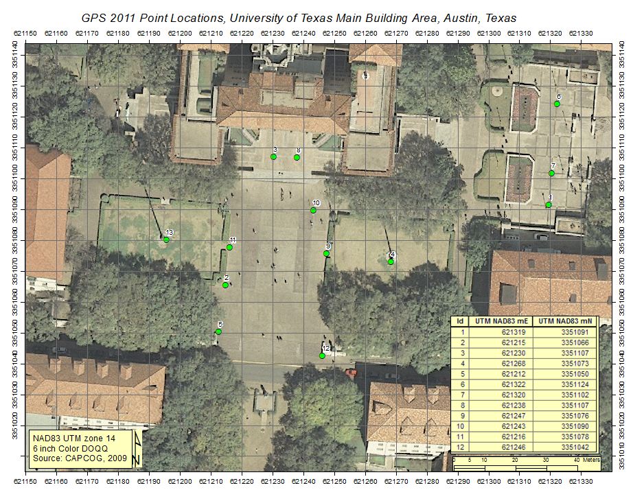
- Points: Points at the two flagpoles.
- L1, L2, L3: Polylines with at least 3 GPS vertices at the edges of
sidewalks.
- P1, P2: Polygons outlining grass areas - capture the vertices
of the 4 corners with
GPS.
You're done.
|
 |